
LiDAR is a radar that emits laser beams to detect characteristic parameters such as the position and velocity of targets. It transmits detection signals (laser light) toward the target, then compares the received reflected signals (target echoes) from the target with the transmitted signals, so as to obtain relevant information of the target including distance, azimuth, velocity, etc.
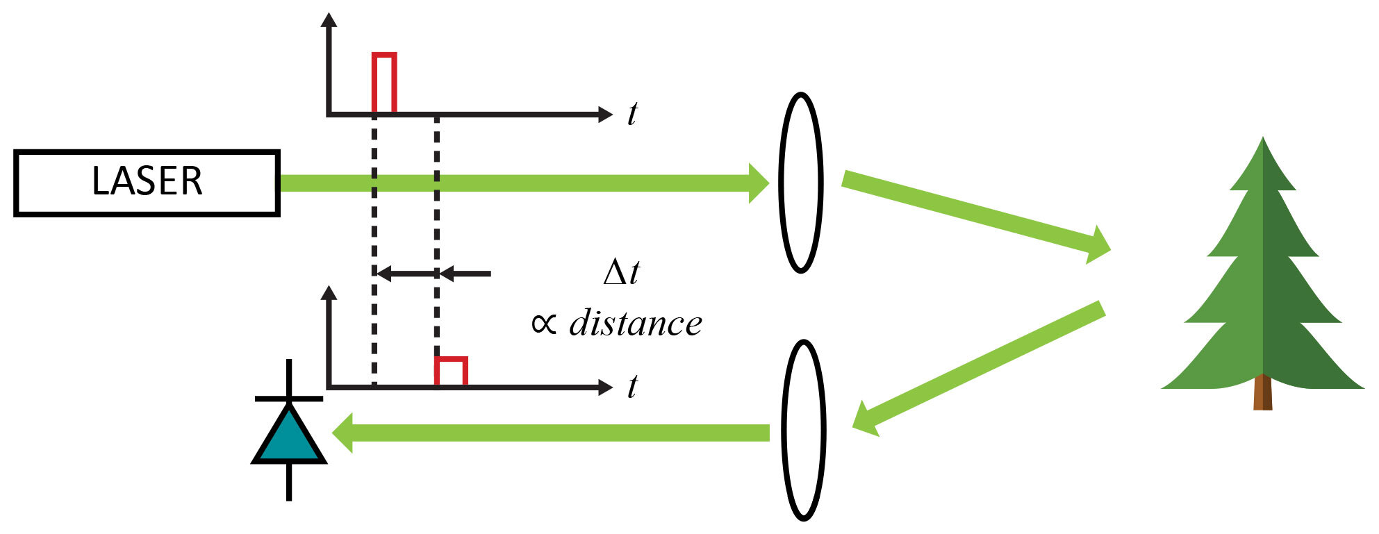
Principle of Laser Measurement
The applications of LiDAR in autonomous driving are as follows:
Road Feature Recognition: Includes road surface conditions, road edges, traffic signs, etc.
SLAM(Simultaneous Localization and Mapping):Real-time mapping of the surrounding environment and self-localization.
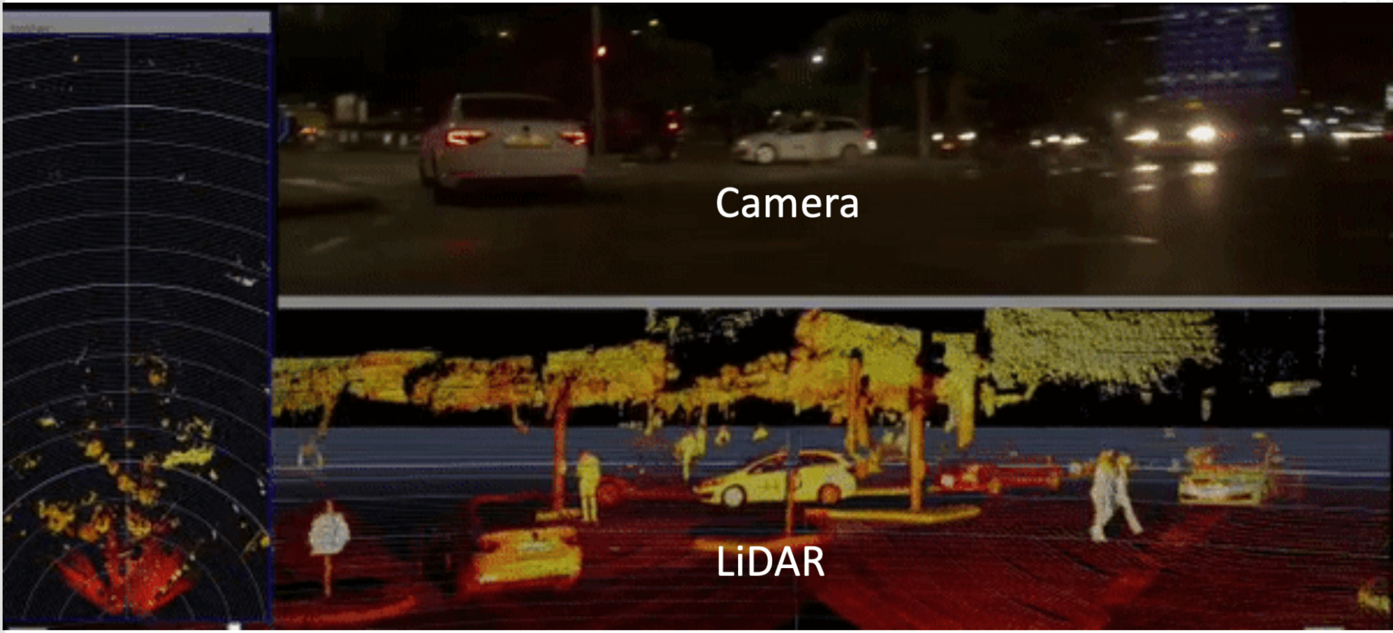
Camera Imaging vs. LiDAR Imaging
The greatest advantage of LiDAR in autonomous driving technology lies in its high precision and good environmental adaptability. Even under harsh weather conditions, LiDAR can still provide accurate 3D information.
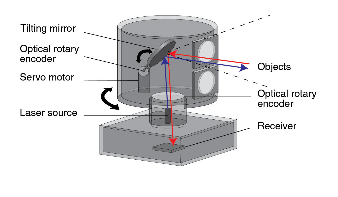
Composition of LiDAR
Positioning and Navigation System: Includes GPS and Inertial Measurement Unit (IMU), used to determine the precise position and orientation of the LiDAR.
Data Processing System: Performs algorithmic processing on the signals output from the analog front-end and outputs the final measured data of the LiDAR.
There are multiple technical implementation schemes for each core component. These schemes affect LiDAR performance metrics, such as ranging distance, accuracy, resolution and sensitivity.
Mechanical LiDAR performs scanning by rotating the transmitter and receiver modules through 360° driven by a motor.
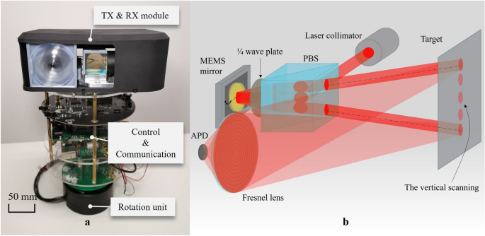
Mechanical‑Rotating LiDAR
Mechanical LiDAR supports 360‑degree omnidirectional measurement and is compatible with high‑energy lasers. Nevertheless, it has a bulky form factor, and its motor suffers substantial wear after long‑term operation.
Hybrid solid‑state LiDAR has three technical routes: prism, rotating‑mirror and MEMS micro‑mirror. For prism and rotating‑mirror architectures, transmitter and receiver modules stay stationary; the motor only drives one or multiple mirrors to rotate.
The MEMS micro‑mirror solution goes one step further by removing the motor. The micro‑mirror executes reciprocating motion driven by electrostatic, electromagnetic, electro‑thermal or piezoelectric forces to realize scanning.

MEMS Micro‑Mirror Laser Scanning
Solid‑state LiDAR has no internal moving mechanical parts. Its two main implementations are Optical Phased Array (OPA) and Flash LiDAR.
OPA LiDAR makes use of optical‑coherence principles. Multiple laser emitters form a transmitting array. By adjusting voltages applied to individual emitters, the phase of light waves from each unit is modulated. Constructive interference occurs along a predefined direction to synthesize a high‑intensity main laser beam pointing to the target angle. Light waves radiated toward other directions generate destructive interference, resulting in near‑zero radiation intensity.

Transmit and Receive Array of Silicon‑based OPA LiDAR
OPA LiDAR achieves high scanning speed and high angular precision, delivering scanning speeds above the MHz range and angular resolution better than one‑thousandth of a degree. It supports arbitrary beam steering within its usable field‑of‑view. However, OPA LiDAR suffers from limited scanning angle, stringent process requirements, high manufacturing difficulty and inherent sidelobe effects.
Flash LiDAR adopts a flash‑type non‑scanning architecture. It emits large‑area laser pulses in a short time window, and highly‑sensitive detectors capture returning light to reconstruct the 3‑D image of target objects. Flash LiDAR contains no scanning module, only transmitter and receiver assemblies.
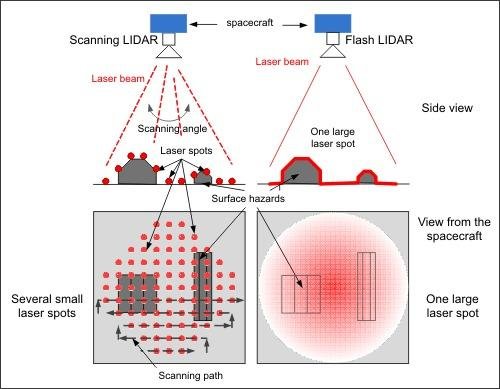
Flash LiDAR versus Scanning LiDAR
Huawei 96‑Line LiDAR
In December 2020, Huawei officially launched its first automotive‑grade 96‑line medium‑long‑range LiDAR.
Key Specifications:
Detection Range: 150 m @10 % reflectivity
Horizontal FOV: 120°, Vertical FOV: 25°
Angular Resolution: 0.25° (H) × 0.26° (V)
Maximum Frame Rate: 25 Hz
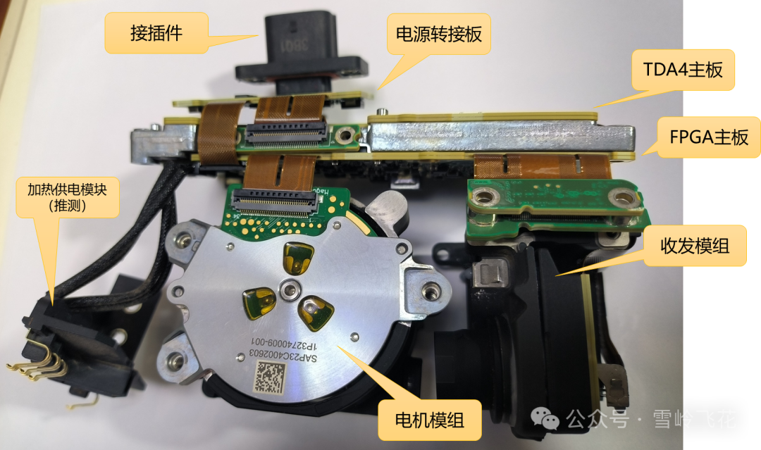
Core Circuit Boards of Huawei 96‑Line LiDAR
Source: Xueling Feihua
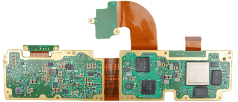
LiDAR Main Board
Source: Zhinen Zhixin
The main‑board assembly is built on rigid‑flex PCB technology. It includes two main boards: the TDA board and the FPGA board. Board edges are gold‑plated. Shielding cans will be mounted subsequently to establish reliable electromagnetic shielding.
Rigid‑flex PCBs reduce the number of inter‑board cables, improve system reliability, save mechanical space and greatly boost assembly efficiency.
Laser Transmitter Board
Two identical laser transmitter boards are deployed. They use EEL (Edge‑Emitting Laser) emitters. Laser diodes are interconnected to the PCB by means of gold‑wire bonding.
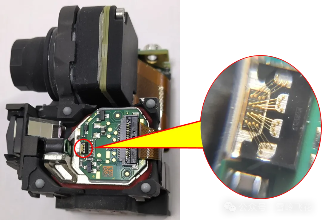
Source: Xueling Feihua
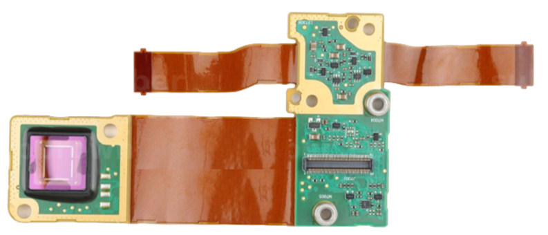
Laser Receiver Board
Source: Zhinen Zhixin
The receiver employs Sony SPAD depth sensors. Rigid‑flex PCB is also implemented on this sub‑assembly. Receiver sensors are bonded to the PCB via bonding wires and protected by adhesive encapsulation.
Reference Sources:
CITIC Securities. In‑depth LiDAR Industry Research: Insights into Intelligent‑Driving Investment Opportunities via Teardowns of Five LiDAR Products
Zhinen Zhixin. Huawei 96‑Line LiDAR Teardown
Xueling Feihua. Detailed Huawei LiDAR Disassembly and System Solution Illustrated in 55 Figures
 WeChat