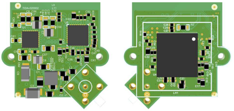
The perception layer of Advanced Driver‑Assistance Systems (ADAS) collects and processes environmental and in‑cabin information via LiDAR, millimeter‑wave radar, camera sensors and ultrasonic sensors.
As the decision‑making layer, the ADAS domain controller fuses multi‑sensor data for decision‑making, generates control strategies and forwards commands to other domain controllers to realize vehicle motion control.
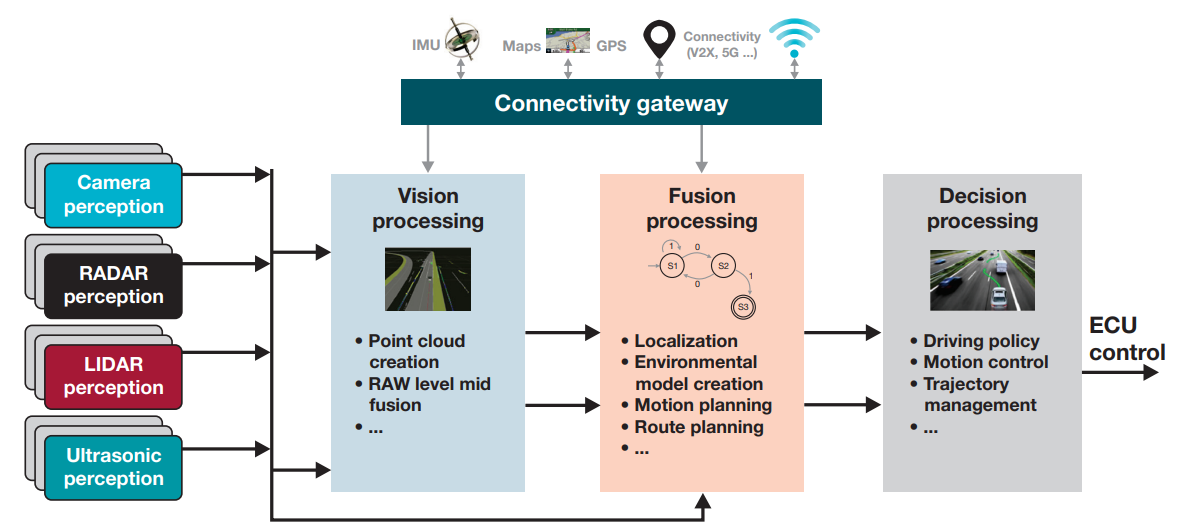
ADAS Processing LogicSource: TI
Millimeter‑Wave Radar: It delivers the longest detection range and performs well on metallic reflections. It remains functional under harsh conditions including night vision, backlight, heavy fog, rain and snow. However, it struggles to detect non‑metallic targets such as pedestrians or cartons.
LiDAR: It achieves medium‑to‑long detection range and favorable reflectivity for non‑metallic objects. It works reliably at night, under backlight, fog, rain and snow. Nevertheless, laser beams can pass through transparent objects such as glass; its performance degrades under intense backlight, heavy rain, blizzard and dense fog.
Ultrasonic Radar: It supports short‑range detection and receives echoes from glass and water surfaces. Yet its readings are susceptible to wind interference and signal absorption by snow and similar substances.
Automotive Camera: Its detection range is determined by lens focal length. It captures visual frames to identify objects and colors, but exhibits poor performance at night, under backlight, heavy rain, blizzard and dense fog.
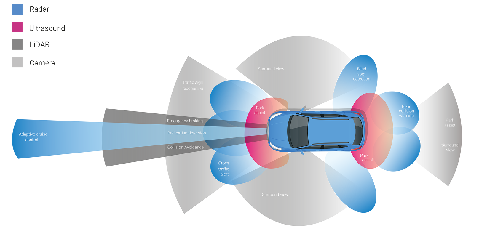
ADAS Sensors and Their Detection Zones
ADAS is categorized into six automation levels from L0 to L5. L0‑L2 belong to driver‑assisted driving, whereas L3‑L5 fall under autonomous driving. Compared with L2, L3 and L4 support conditional autonomous driving functions including TJP (Traffic‑Jam Pilot), HWP (Highway Pilot), CP (City Pilot) and AVP (Automated Valet Parking).
According to Roland Berger, the penetration rate of L2/L2+ will reach 36 % and L3 will hit 8 % by 2025. Mass‑produced vehicles are currently transitioning from L2 toward L3 ADAS capability.
Perception Camera: Mounted on the upper windshield with a wide field‑of‑view. It enables autonomous‑driving and driver‑assistance features such as LKA (Lane‑Keep Assist), LCA (Lane‑Change Assist) and AEB (Automatic Emergency Braking), safeguarding forward‑driving safety.
Surround‑View Camera: Units are fitted at the front, rear, left and right sides of the vehicle, covering approximately 1‑meter perimeter around the car. It supports parking assistance and improves peripheral vehicle safety.
Due to divergent functions and mounting positions, automotive cameras differ significantly in hardware design. Limited installation space for perception and driver‑monitoring cameras frequently calls for integrated rigid‑flex PCB architectures. Given its special form‑factor constraints above the windshield, the perception camera often adopts a discrete design with separate sensor board and main board.
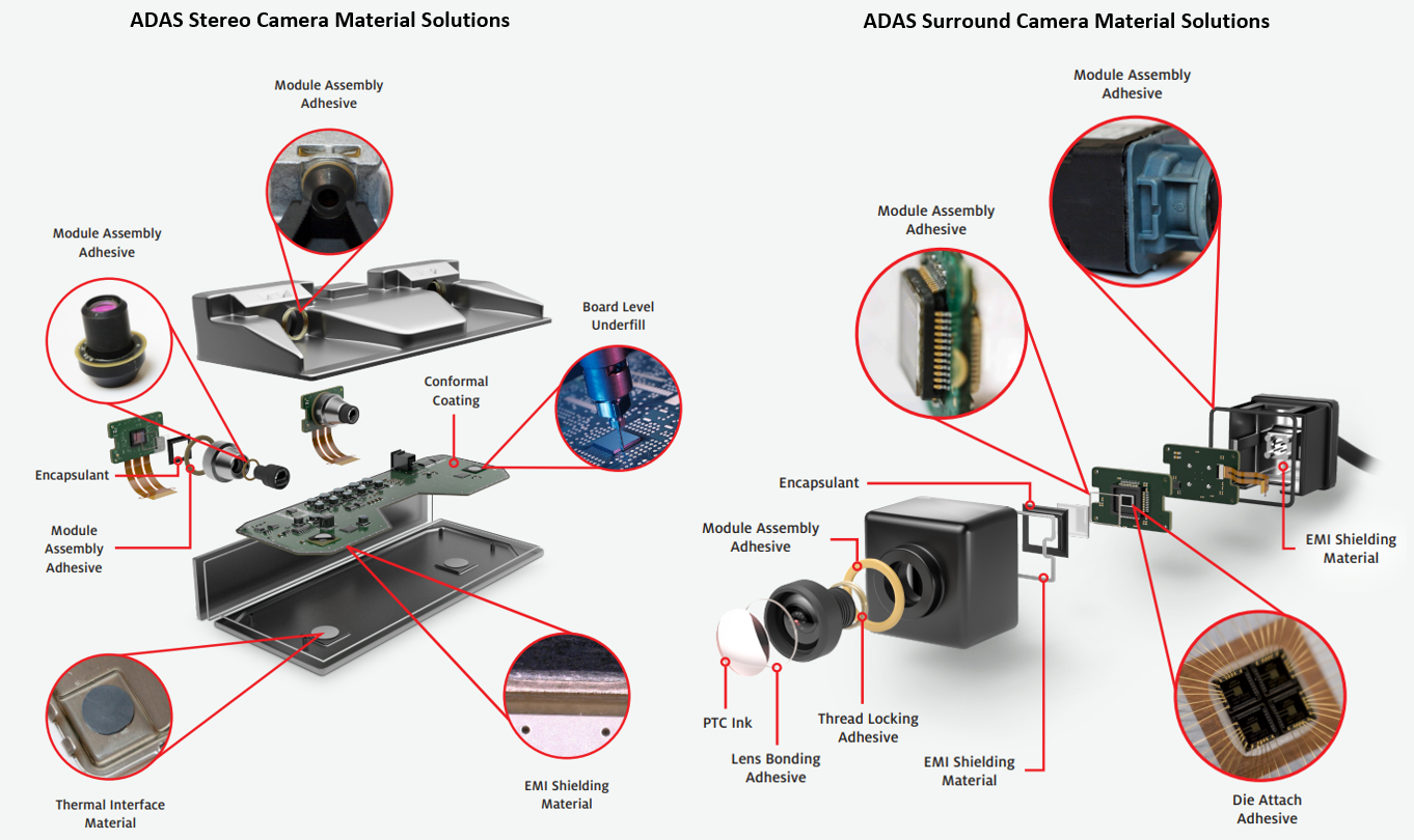
Internal Construction of Perception Camera and Surround‑View Camera
The image sensor captures scenes through the camera lens and converts optical input into electrical signals. Image data is transmitted over high‑speed interfaces to the SoC for processing. Processed outputs are sent from the domain‑controller MCU to external ECU to trigger corresponding actions.
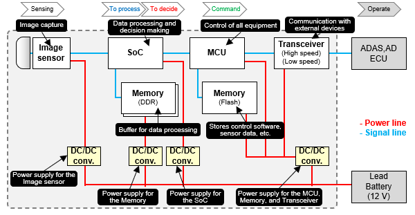
Block Diagram of Perception CameraSource: Panasonic
DC/DC Converter: Steps down lead‑acid‑battery voltage to working voltages for individual components.
Different from perception and driver‑monitoring cameras, surround‑view systems stitch video feeds from multiple vehicle‑mounted cameras into a single omnidirectional top‑view image. Massive real‑time data flows transfer between camera ECUs and the surround‑view ECU. An FPGA on the surround‑view ECU aggregates multi‑channel video streams into the composite surround view and performs real‑time image enhancement. Remaining hardware configurations match those of perception / driver‑monitoring cameras.
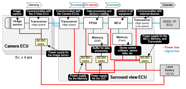
Block Diagram of Surround‑View CameraSource: Panasonic
This section takes the Sony IMX390 2‑megapixel camera paired with the 4‑Gbps serializer DS90UB953 as the reference solution.
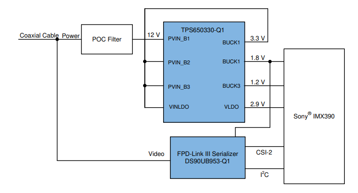
Solution Block DiagramSource: TI
3D Rendering of PCB LayoutSource: TI
Automotive‑camera PCB design must satisfy AEC‑Q100 grade requirements for ambient temperature, vibration, service lifetime and complex electromagnetic environments. Laminate material and stack‑up schemes shall be selected to balance performance targets and mechanical dimensional limits under extreme operating scenarios.
This reference design requires a minimum 4‑layer stack‑up with dedicated power and ground planes. For a 4‑layer implementation, Layer 2 must serve as solid ground plane. Since most switching devices are placed on the top layer, this stack‑up minimizes stray inductance introduced by vias within signal return paths.
A 6‑layer stack‑up is implemented in this reference design to ease BGA fan‑out and routing complexity.
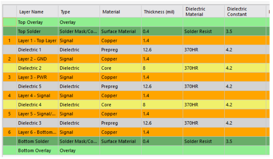
Stack‑up SchemeSource: TI
Maintain 50 Ω single‑ended impedance for coaxial transmission‑line traces; minimize physical length for these 50‑Ω controlled‑impedance segments.
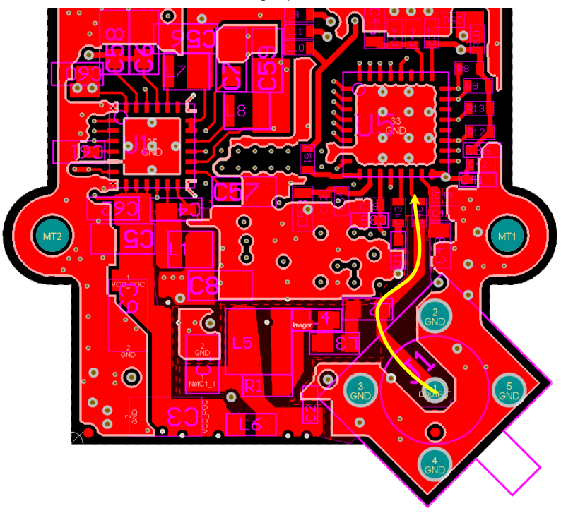
Minimize Trace Length for 50‑Ω Controlled‑Impedance TracesSource: TI
Reference Sources:
- What cameras are installed in ADAS and AD systems?‑Panasonic
- Automotive 2‑Mpixel Camera‑Module Reference Design with MIPI CSI‑2, PMIC, FPD‑Link III and POC – Texas Instruments
 WeChat