
Based on orbital altitude, communication satellites are categorized into Low‑Earth‑Orbit (LEO), Medium‑Earth‑Orbit (MEO), and Geostationary‑Earth‑Orbit (GEO) communication satellites.
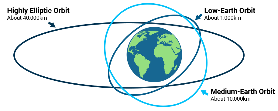
LEO satellites operate at altitudes ranging from 300 km to 2000 km. Thanks to low orbital height, LEO systems deliver short signal propagation latency and low link loss. Requirements for satellites and user terminals are moderate, permitting compact mini‑satellite receivers and handheld user devices. Nevertheless, each LEO satellite covers a limited ground footprint; global constellation coverage calls for a large quantity of satellites.
MEO satellites orbit between 2000 km and 35 786 km. They exhibit higher transmission latency compared with LEO but offer larger coverage areas, requiring fewer satellites for global networking. The Inmarsat system serves as a typical MEO implementation.
Satellites function as communication repeaters: they receive, amplify radio signals transmitted from ground facilities and forward them to other ground stations. At present, GEO satellites are widely adopted for global blanket coverage.
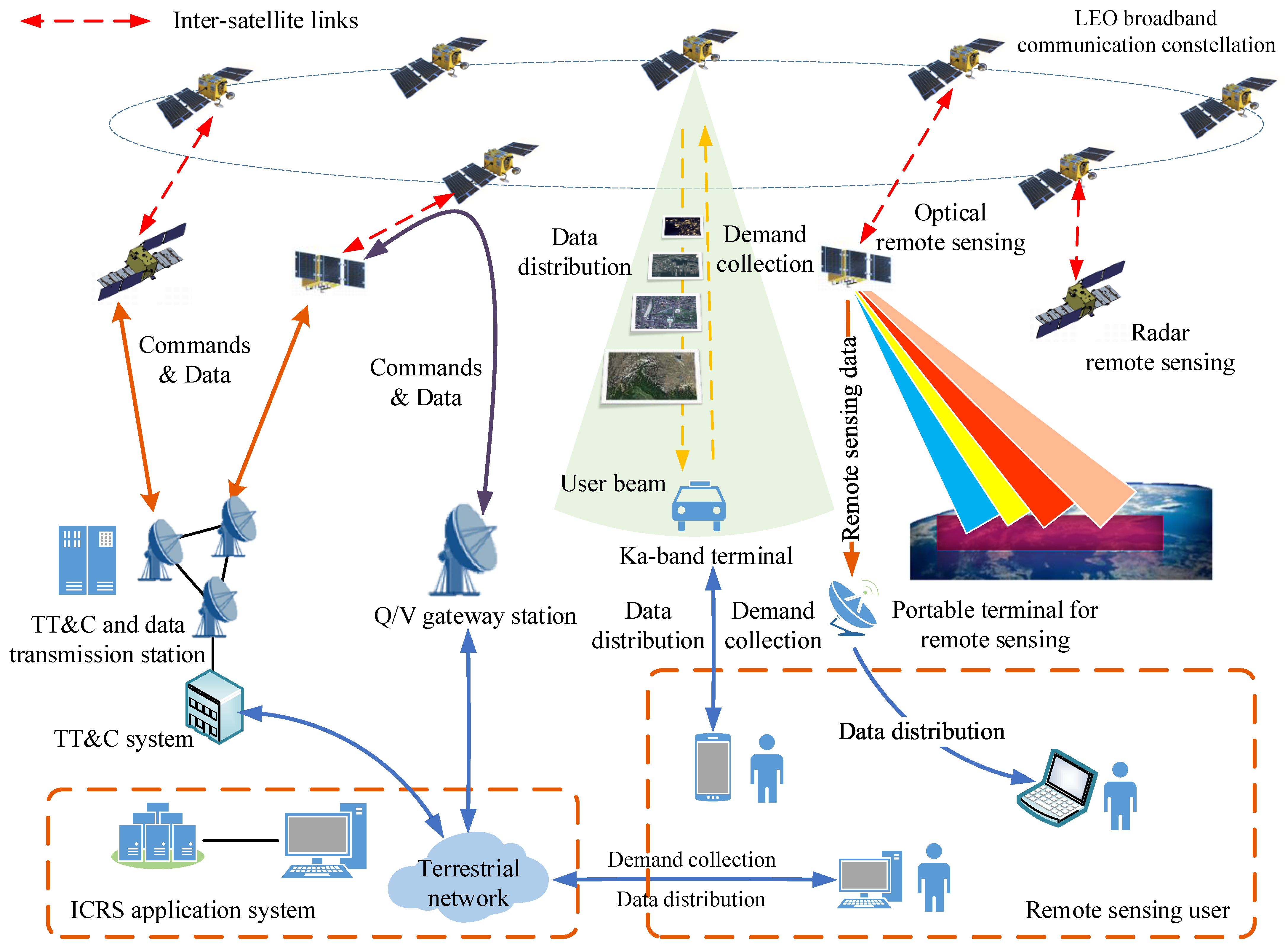
Satellite internet relies on high‑throughput LEO satellites in space to provide wide‑band coverage characterized by high bandwidth and low latency. These satellite constellations act as space‑based base stations, delivering performance comparable to terrestrial mobile‑communication networks.
Satellite manufacturing comprises two core parts: satellite platform and payload. Payloads are the functional heart of communication satellites. Communication‑satellite payloads include antenna subsystems, transponders and inter‑satellite links.
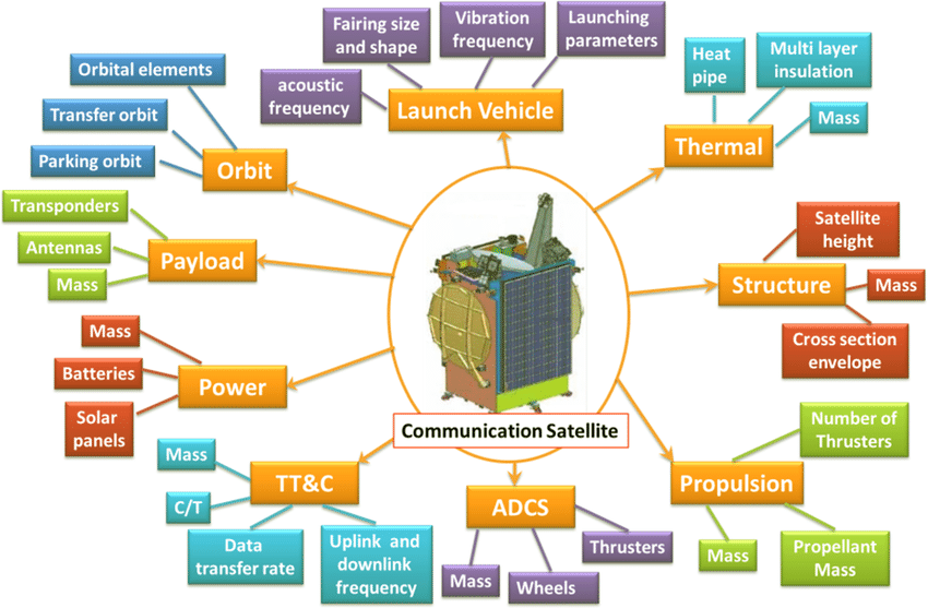
The antenna subsystem is critical within satellite payloads. Phased‑array antennas represent today’s mainstream technology, where T/R (Transmit/Receive) modules constitute the core building block, accounting for over 50 % of total cost for space‑borne antenna subsystems.
A multi‑beam phased‑array antenna leverages beam‑forming networks to generate multiple independent high‑gain beams simultaneously, featuring high flexibility and wide‑angle scanning capability. Key technical challenges for LEO‑borne multi‑beam phased‑array antennas include:
Rapid test technology for multi‑beam phased‑array antennas
The Ku‑band multi‑beam phased‑array antenna deployed on Starlink satellites represents state‑of‑the‑art performance for civil communication satellites. It adopts hopping‑beam coverage and a tile‑type architecture with progressively sparse element arrangement from center outward. The stack consists of antenna‑array layer, reflection layer, multiplexer feed layer and beam‑forming layer. Beam‑forming is implemented by 8‑channel, 8‑beam multi‑function chips containing phase shifters. Multiple antenna beams and phase scanning are realized by multi‑function chips, while amplitude weighting is achieved via array layout.

(Figure: Antennas of Communication Satellite)
Processing transponders emerged alongside large‑scale digital‑processing advancement. Distinct from transparent types, they perform signal demodulation and regeneration to remodel base‑band waveforms.
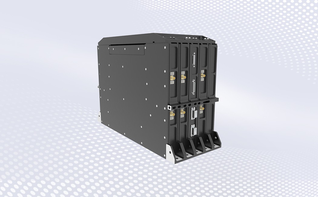
(Figure: 2nd‑generation Space‑borne Base‑Station from Xingyi Lianxin)
Laser communication modulates voice, data and other information onto laser carriers for transmission. Satellite laser communication delivers huge transmission capacity, enables seamless integration with other communication technologies and reduces intermediate decoding overhead, enabling high‑speed inter‑satellite connectivity.
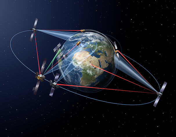
(Figure: Satellite Laser Communication)
Space‑borne laser‑communication systems are highly complex and span optics, mechanics and electronics. Subsystems include optical transceivers, Acquisition, Pointing and Tracking (ATP) units, optical assemblies, power‑distribution modules and thermal‑control subsystems.
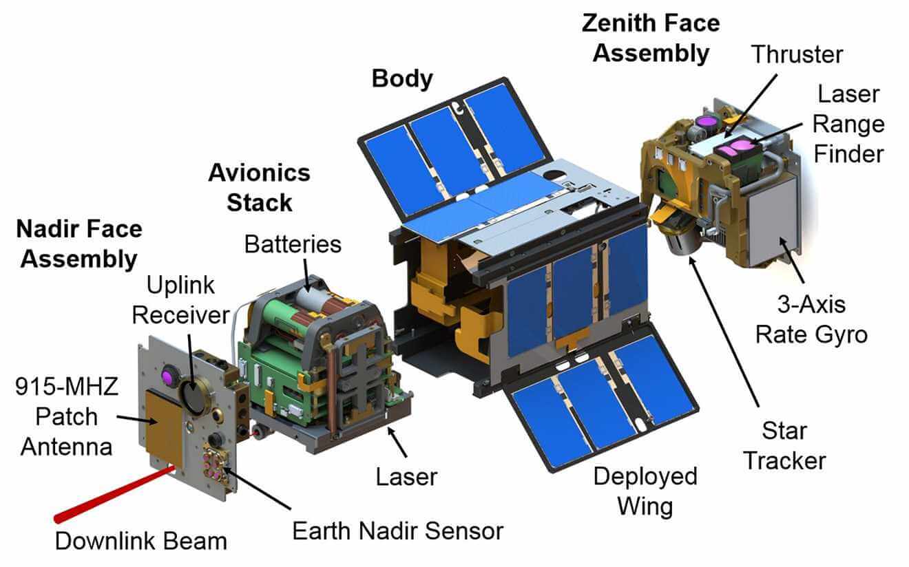
LEO ground antennas must track fast‑moving satellites with rapid beam‑switching capability. Cost‑effective phased‑array antennas are widely deployed for signal stability. Without mechanical rotation, beam direction is adjusted purely by modifying signal phase to lock onto satellites; a single antenna can serve multiple satellites concurrently.
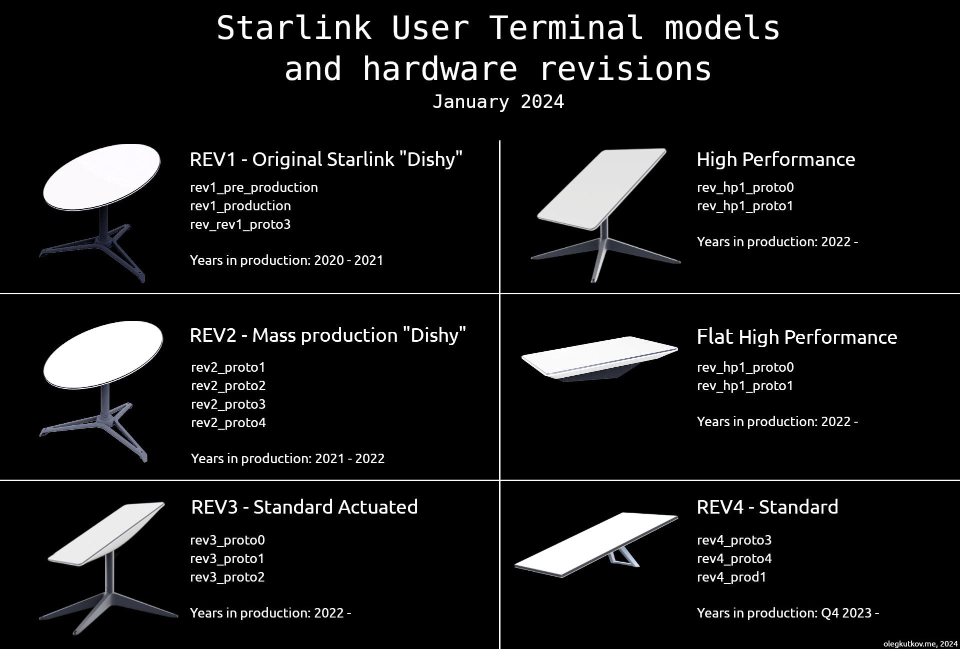
(Figure: Starlink User Terminal Models and Hardware Revisions)
The Starlink ground receiver adopts a six‑layer mechanical stack, from top to bottom: antenna radome, cellular mesh plate, rubber honeycomb panel, PCBA assembly, aluminum structural backplane and base pedestal.

1)Radome: Protects antenna elements against environmental stressors.
2)Honeycomb isolation array: Laminates antenna stack layers, isolates individual antenna elements to mitigate mutual coupling interference, improving beam directivity and overall antenna efficiency.
3)Antenna panel: Integrates 1280 antenna elements including peripheral dummy elements for surface‑wave absorption and wave‑impedance matching.
4)RF board: Populated with 80 large‑form‑factor RF chips plus 640 small RF chips responsible for signal transmitting and receiving. The RF board is fabricated with CMOS process to control BOM cost.
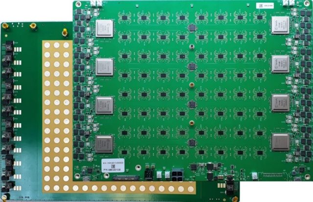
(Figure: RF‑board PCBA of Satixfy Ground Receiver)
Starlink gained more than one million new subscribers in 2023. Calculated with 1:1 terminal‑inventory ratio and standard‑terminal price of USD 600, its terminal‑market value exceeded USD 900 million in 2023.
 WeChat